

fedeleluigi
-
Posts
206 -
Joined
Content Type
Profiles
Forums
Events
Posts posted by fedeleluigi
-
-
If any member has the engineering drawings (possibly not resized) of the AR9-90 schematic and crossover assembly, please post them. If the files are too large to be embedded here, please post me a PM.
Unfortunately, it seems that they are not present in the AR Drawings except that of the AR90 crossover assembly.
-
On 12/4/2020 at 4:21 AM, r_laski said:


I'm posting this AR9 crossover schematic and picture to show there is a second 1.37mH (6) coil in the Upper MidRange (UMR). It is the one to the right in the picture. One (outside) wire is connected to the 24uF cap and 0.2mH coil. The other (inside) wire is connected to the upper black (-) binding post. The other 1.37mH (6) coil is on the lower left corner. One wire (outside) is connected to the 0.2mH coil, orange wire to UMR (+), and 8uF cap. The other wire (inside) is connected to the 6 Ohm resistor, as shown in the schematic (resistor not in the picture).
In 2009 mluong303 wrote about the same mistake on the CSP schematic and the correction that you reported.
Contrary to AR9 schematic in the CSP library, the AR90 schematic (original engineering drawing) is correct concerning this point. It also has the 8uF capacitor instead of the 6uF (on the CSP schematic) in parallel with the upper midrange. On the AR90, the HR, UMR and LMR are connected out of phase with respect to the woofers.

Here a little inconsistency in the original AR90 schematic is reported (with respect to the crossover assembly).
-
Hi Jay,
Ken Kizer (aka dxho @dxho ) did an excellent job and I take this opportunity to thank him:
https://community.classicspeakerpages.net/topic/13990-access-to-ar-drawings/?do=findComment&comment=136564
-
13 hours ago, Jay said:


Jay, these pictures you posted are the pictures of a Tonegen 1210040-xx woofer used as replacement part for the 200004-2 original woofer. The Tonegen part # is printed under the 200004-2 label. Contrary to what the label reports, I don't think this woofer was ever built in the USA. Note the big resistor.
-
Jay,
AR was very reluctant to change item part numbers. When it did, in general something really important had changed!
On the AR drawings you can see that the on axis frequency responses of the 200040-0 and 200004-2 woofers are rather similar but the former has a 2-3 dB higher sensitivity than the latter.
The Tonegen 1210040-xx woofer you posted was the replacement part for the 200040-0 woofer. When it was used as replacement part for the 200004-2 woofer it had a big resistor (probably to be connected in series to "tame" its greater sensitivity). Unfortunately I have never seen an official AR or ABtech document showing how to connect this Tonegen replacement part in the AR2ax, 5, LST2, 14 and 12.
-
19 hours ago, Jay said:
I bought new AR48b speakers back in the mid-1980's and had the surrounds of the woofers replaced once by a stereo repair shop around 2000 and a couple years ago I replaced the surrounds myself.
factory coating of the cones?


Hi Jay,
I think that around 2000 the stereo repair shop reconed your 200040-0 woofers instead of just replacing the foam surrounds!
The part # of the 200040-0 original paper cone is 203043x and is printed on the back of the paper cone itself.
-
-
On 2/22/2021 at 9:09 PM, Stevie F said:
I can see broken wire on the positive side, on the tweeter surface
If that is the only problem, the tweeter is repairable but it is a very delicate procedure and should be done by very experienced hands.
The 200014-0 / -1 tweeters are very rare and very hard to find in the used market. They are different from the
They differ both from the 200005 tweeter (used in the AR-6, 7, 8 and 4xa) and from the 200014-3 tweeter (used in the AR-18, 17 and 25) and cannot be interchanged with them.
The AR-MST / 1 (USA) and the AR-MST improved (Europe) have 3 tweeters in parallel and, for this reason, do require high impedance tweeters. So, differently from 200005 and 200014-3 tweeters, the 200014-0 and 200014-1 units are high impedance tweeters and have a DC resistance of about 10 Ohms (from 9.5 to 10.5).Unfortunately, in some old threads I have read about people who changed the first European version of the AR-MST (the one with 4 tweeters connected in series-parallel) to the "improved" version by using the MST improved crossover and connecting three 200005 tweeters in parallel. By doing so, the impedance at 9000 Hz is about 1.7 Ohm! Without considering the phase!
-
On 1/9/2021 at 1:45 AM, Chris1this1 said:
Resurrecting this thread, since I am working 9LS speakers. I have some questions for the crossover experts. On the woofer and LMR shunt caps, there is a 0.5 ohm resistor. That small value in the scheme of things seems almost negligible, so what is its purpose?
The next question, is not only are 1.5 ohm and 2.5 ohm resistors added in to attenuate the LMR and UMR, but the polarity of the tweeter is reversed, as well as the 5uF cap right before the tweeter + terminal (ls crossover) is eliminated. Why reverse the polarity on the improved, and why get rid of that cap?
Im interested in finding out these answers, because I am planning on implementing a LS/LSI switch, to accomplish adding or the 1.5ohm and 2.5 ohm resistors, and also shorting the 5uF tweeter cap when LSi is selected, and of course the opposite when LS is selected. Easily implemented with a 3 pole single throw switch. However, reversing the tweeter polarity wouldn't be possible without another two poles or an additional switch, which id like to avoid. Do you folks think reversing the tweeter polarity would be necessary when using the LSi circuit?
The 0.5 Ohm resistors change the damping of the filter cells and must not be removed!
The polarity reversal for the tweeter connections depends on the fact that the high pass filter is of the third electrical order for the AR-9LS while it is of the second electrical order for the AR-9LSI. So, if you change the filter you must also change the polarity unless you can verify the result with appropriate FR measurements.The crossover changes made by the AR engineers in the AR-9LSI crossover are very small. The AR-9LSI used the "new" Tonegen drivers and the small changes made in the LSI crossover were most likely made primarily to handle the small sensitivity an FR differences of the new Japanese drivers compared to the US-made ones. So, if your speakers have the original (made in USA) drivers (tweeter-midrange and lower midrange), my personal advice is not to modify the original crossover. If these small changes had led to any improvements, you can rest assured that AR engineers would have done them long before the introduction of the 9LSI as any advanced hobbyist would!
In any case, I would not be surprised at all if most audiophiles would say, due to the "improved" suggestion, that the 9LS sounds better with the 9LSI crossover...😀!
-
On 12/10/2020 at 7:07 PM, Sonnar said:
Curves are identical in the bass and midbass region, same or similar woofer , they 're absolutely comparable.
Conversely, they 're very different in midrange and highrange, different loudspeakers, different crossover.
As Tom Tyson said , the AR 3's tweeter " had a gently rising characteristic " , as everyone can see by the graphics , while AR 3a has a well-known gentle roll-off starting at 5 Khz .
I'm not saying which one sounds better , but they 're surely different speakers, different sounding.
Adriano, for those who know a little about acoustics, those measurements are not comparable.

AES paper AR-3a 2Pi frequency response measured on axis in AR "particular" anechoic chamber (please, see my previous post for details).
I do hope you can appreciate the great difference between Fig.9 (4Pi anechoic response on axis) and Fig. 5 (2Pi frequency response measured in AR "particular" anechoic chamber) graphs shown in the AES paper for the same AR-3a speaker. So, as I wrote before, you cannot compare apples with oranges.
Moreover, it is not a question of whether the AR-3 is better than the AR-3a or vice versa. The problem is that what you say does not correspond to the truth. For many years, you have had the theory that the AR-3 and AR-3a were speakers conceived and designed differently and consequently their sound was very different. However you have never been able to prove this theory of yours.
Furthermore, you have never taken into account a lot of data that has been provided to you over the years. In summary:
-First of all, no company in the world would replace a best-selling loudspeaker such as AR-3 with one that is very, or even totally, different in sound. Moreover at AR they pursued the accuracy of reproduction and not a particular sound philosophy! Or, if you prefer, the sound philosophy of Villchur, Allison and many other talented people who worked at AR was exactly the same: to make a very accurate speaker!
-Second, all the reviews from that period claimed the differences in AR-3 and AR-3a sound were rather subtle and not earthshacking.
-Finally, even the testimonies of very experienced people who were able to compare them when both AR-3 and AR-3a were new, state the same thing: the sound of the two speaker systems was ultimately very similar.
For all these reasons, I previously quoted an old Tom Tyson's post where he says: “The AR-3a certainly improved upon the same formula that made the AR-3 such a good speaker, but the refinements were quite subtle. For example, there are no pronounced differences in the measured response of the two speakers - there are more similarities than differences. I heard a "new" AR-3 and a "new" AR-3a compared in the AR Music Room in 1967, and the "new" speakers sounded much more alike than have been described by some people on these pages. The biggest problem I see is that it is difficult to find AR-3s today, after so many years, that perform as they did when new. This is also applies to the AR-3a's 3/4-inch tweeter, as well.”
You seem to want to convince yourself that your AR-3s still sound like they did when they were brand new!
Unfortunately, it is well known that the AR-3's midranges very often age poorly and badly as the whitish material around the dome unfortunately hardens. Until it completely hardens, this causes a progressive increase in the unit resonant frequency which progressively results in a low output in the mid-range band and an increased output in the high-range band (just like when you tighten the strings of a guitar more and more: the "basses" progressively decrease and the "highs" conversely increase). That's why "no midrange” and “sparkling highs" as you say in the first post! That’s correct! That’s the result of AR-3 midrange aging until, ultimately, the output will be very, very low at all frequencies like some members described in this forum.

Reviews that compared AR-3 and AR-3a

-

-

Electronics World enterely reprinted Julian Hirsch's review.
-
On 12/1/2020 at 11:03 PM, Sonnar said:
These measurements were made in half space , absolutely comparable.
As I mentioned, the graphs of the frequency response curves you posted are not comparable for several reasons.
In summary, you can correctly compare measurements of two or more speaker systems only if they are acquired according to the same standards.
We are sufficiently familiar with the "standards" used by AR through the AES paper (https://www.aes.org/e-lib/browse.cfm?elib=2058) from which the AR-3a graph you posted comes from but we know nothing about the "standards" adopted by High Fidelity Magazine. In the AR-3 article they just say: “The effects at 150 to 250 Hz cps are ground reflections and diffraction effects (the speaker was lying on its back, facing upwards for these measurements)”, and for the higher frequencies : “These measurements were made with both midrange and tweeter level controls at the indicated flat positions.
But nothing is specified about the acoustic characteristics of the chamber in which the measurements were made, the positioning of the microphone, the equipment used, etc. It is not even specified whether the speaker system was flush with the floor as AR did in some of its measurements shown in the AES paper I mentioned.
In the AES paper, as regards the 2Pi measurements, AR says: “Our main anechoic chamber has non-reflective wedges on only 5 of its interior surfaces. The sixth is smooth concrete, with an opening in its center; speakers to be tested are placed at this opening with suitable adapter baffles so that they are flush with the inside chamber wall. In this manner a 2Pi radiation angle is obtained with minimum discontinuity”.
But what is even more important is that the AR-3a frequency response graph you posted is not the correct one. In fact, it refers to the AR-3a system measured in 4Pi anechoic environment: Fig.9 in the AES paper (please see the attached graph).
In the AES paper you can read: “The picture becomes far more complex when the same system (AR-3a, Ed.) is measured in 4Pi environment. We took this AR-3a to the large walk-in anechoic chamber at Harvard Acoustics Laboratory, and repeated the measurements there. Fig. 8 shows on-axis response of the individual speakers of the system, in the cabinet and with molding in place. Mid-range and tweeter curves are shown for both the normal and maximum level control settings. The most obvious feature of Fig. 8 is the woofer response. There is a continuous down-hill slide from about 400 Hz, at which frequency the cabinet is a reasonably effective 2Pi baffle, to about 170 Hz, and then a flat response below that frequency. At 170 Hz and below the radiation angle is 4Pi steradians and the output, quite predictably, is lower than it was into a 2Pi angle. Molding and cabinet-edge diffraction are clearly at work on the axial response curves of the mid-range unit. Fig. 9 is the on-axis system curve, with molding, level controls at maximum.”

-
On 11/30/2020 at 7:58 PM, Sonnar said:
No, AR 3 sounds more transparent and sparkling, curves are very different in mid-high region.


Adriano,
No doubt that the charts you posted show two very different curves. But they were acquired in different situations and ways and for this reason they are not comparable each other otherwise you compare apples with oranges.
-
@AadamsThank you for the link!
Tom Tyson also explained the reasons for the sonic differences in the second part of his post (I highlighted it in red). I agree with him.
On 8/25/2005 at 4:05 AM, tysontom said:I really don't have a preference. I have such great respect for both speakers that I enjoy listening to either system. Clearly, the AR-3a was a improvement over the AR-3 in several respects, such as off-axis response and power-handling. The AR-3, however, received higher critical acclaim when it was introduced, and it set the standard of performance, but it came out (technically) nine years prior to the AR-3a. It has become a great classic in every since of the word. The AR-3a certainly improved upon the same formula that made the AR-3 such a good speaker, but the refinements were quite subtle. For example, there are no pronounced differences in the measured response of the two speakers -- there are more similarities than differences. I heard a "new" AR-3 and a "new" AR-3a compared in the AR Music Room in 1967, and the "new" speakers sounded much more alike than have been described by some people on these pages.
The biggest problem I see is that it is difficult to find AR-3s today, after so many years, that perform as they did when new. This is also applies to the AR-3a's 3/4-inch tweeter, as well. The glues become brittle; the foam-rubber damping rings harden; the suspensions on the tweeters change through time so that the performance of this speaker has likely deteriorated slightly through time. When AR was fabricating these tweeters, the rejection-rate on drivers was very high; today I doubt that any of them would pass with flying colors, but perhaps that is to be expected with anything that is thirty- or forty-years old.
I wanted to share the Berkovitz study on the piano-vs.-AR-3 because it showed that the AR-3 was (once again) capable of very accurate replication of the signal source. I have always felt this to be the real definition of "high fidelity." It is true that it could not duplicate the radpat of a piano -- no speaker could -- but the AR-3 was clearly able to accurately reproduce the electrical signal it received, as graphically shown in the oscilloscope images. This was especially noteworthy in that the test was originally performed to determine the output requirements of an amplifier to reproduce "live" levels of a piano using a typical, low-efficiency speaker (without regard to the speaker model), and the accuracy results were strictly coincidental to the power-requirement studies.
--Tom Tyson
Although many people believe that the AR-3a project is essentially the work of Allison and McShane, personally, I have always believed that Vilchur certainly and actively participated in that project that probably began immediately after the introduction of the AR-3 in 1958. Taking into account Villchur's life after the sale of Acoustic Reseach to Teledyne (in 1967, a few months before AR-3a was introduced) I can't believe that in the years before the sale of his company Villchur only dealt with other issues of the company except speaker design. So, personally, I think there was no discontinuity with Villchur's "sound philosophy" with the introduction of AR-3a and the sound differences that today emerge when comparing AR-3 to AR-3a essentially depend on their different aging.
-
@Anders Nilsson I do think that the paper collar of the voice coil is damaged or even totally cracked and this generally causes that kind of problems you are hearing. Unfortunately the collar damage is a problem of the 12" ferrite woofer produced before about 1977. Then AR switched to aluminum for the voice coil formers and it is much more stronger than paper. On page 5 (fig. 2.4 and 2.5) of "Restoring the AR-3a" you can see the characteristic final crack of the paper voice coil collar.
-
I saw on Ebay two "strange" 12" Alnico woofers and I wish to share their pictures here because, as far as I remember, this is the first time I've seen this peculiar type of 12" Alnico woofer.
- They date Jul-Aug and Sep 1968 respectively.
- Although the magnet is Alnico, the cone and surround are not typical of the 12" Alnico woofers. In fact they are the same as those used in the "earliest" generation of the ferrite woofer. In other words it is used a smooth paper cone with a damping ring and the surround is made of foam.
- The baskets have the mesh screens (they were removed in woofer #2).
- Differently from the "earliest" generation of the ferrite woofers, the "classic" masonite ring for the surround is present (in woofer #1 it was removed).
- The spider seems particular (unfortunately the photo is not very clear).
- The peculiar remains of old foam surrounds do seem to come from the original AR foam surrounds (that is both woofers have never been refoamed previously). This important aspect would rule out that these woofers come from some restoration using some parts coming from the "first" generation ferrite woofers. In other words these alnico woofers do seem original!
- Dust caps are distinctive.
#1 woofer:

The masonite ring has been removed (see the other woofer)


#2 woofer:


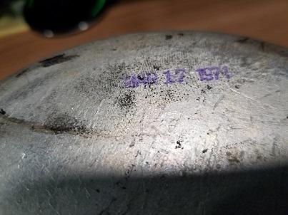
"First" generation of 12" ferrite woofer (Mar 17 1971):


-
On 6/10/2020 at 5:28 PM, Michele said:
I measured the impedance of my LST and shoved on my Fluke instrument 10,4 Ohms: looking into cross over layout there is one 10 Ohms resistor connected in parallel of capacitor
Ciao Michele,
If your AR-LST crossover has a 10 Ohm resistor in parallel with the 2500 uF cap you are basically measuring the resistance of that resistor.
You can see some AR-LST measurements here
AR_LST impedance at two different switch positions (2 and 6)

-
On 3/5/2020 at 12:11 PM, jomede said:
So are mine the 1991 AR3a Replicas or the Limited?
It's hard to say.
Unfortunately I have never seen and examined the AR-3a Limited. All I know about it derive from some members of this forum especially John O'Hanlon (forum nickname Johnieo @johnieo) and Mihn Luong (forum nickname mluong303 @mluong303). Unfortunately, they have not been writing on these pages for a long time. If they still read the pages of this forum, I take the opportunity to greet them.
Some aspects of your AR-3a are similar to those of the AR-3a Limited others to those of the Italian AR-3a Replica. For instance your 3a crossover (components, PCB and wires) is the same as that of the 3a Limited (see the photo posted by Mloung303 in this thread http://www.classicspeakerpages.net/IP.Board/index.php?/topic/5330-ar-3a-reissue/&do=findComment&comment=78855 ) . On the other hand, the fact that the furniture seems to be veneered with real wood is an aspect similar to the AR-3a Replica. However, like the cabinets of modern speaker the AR-3a Replica has a veneer surface much more refined and smoth than that of the Original AR 3a.
Johnieo said that: “the Genuine AR-3a Limited had a "picture frame" front similar to the US AR-3a, with the exception that its width was 1-inch instead of 1-1/4 inch” (http://www.classicspeakerpages.net/IP.Board/index.php?/topic/5330-ar-3a-reissue/&do=findComment&comment=78841 )
The AR-3a Replica picture frame molding is 31.8 mm (1.252 in) thick at the “base” and 31.4 mm (1.236 in) thick at the “top” and, moreover, unlike original AR-3a the inner edge is not squared but round (see pictures).
So please check the thickness and the edge of you AR-3a picture frame molding and please let us know.
In the AR-3a Replica I examined, all the screws are metric but I don’t know if there was some variations during their production. So, please check also your AR 3a screws as this can be a useful information.
Today I have taken my brother’s AR-3a Replica apart to take some photos of its crossover. I have also taken some photos in comparision with a genuine old AR-3a that I should restore. These AR 3a Replicas were first bought by a friend that later gave them to my brother since in his listening room they never sounded well. My friend replaced the original caps and wires with “better components” in the hope that the sound could improve but to our ears nothing changed probably because the original electrolyte NP caps were new. The original tweeter cap was a generic polypropylene (or polyester I don’t remember) one but my friend replaced even that. The original connection wires were common type electric wires that my friend replaced with Cardas cables.
PS If you don’t mind could you please post also the part number of the other tweeter of your AR-3as? Unfortunately the part number you posted is not clear and these tweeters are rare and their part number variation are still an enigma for me.
Thank you


the AR-3a Replica upgraded crossover: bobbins, L-pads, PCB are genuine. Original capacitors, resistor and wires were replaced with "better" components.

The original crossover

Original AR-3a and AR-3a Replica on the left and right respectively


differences in the wood veneers: on the left the Original AR-3a, on the right the Italian AR-3a Replica. The wood veneer surface of the AR-3a Replica is much more refined and smoth than that of the original AR-3a but this aspect can't be fully appreciated by the photo.

AR-3a Replica picture frame molding. The inner edge is round. The picture frame molding is 31.8 mm (1.252 in) thick at the “base” and 31.4 mm (1.236 in) thick at the “top”.


Original 3a picture frame molding. The inner edge is squared. The thicness is the same both at the base and the top (31.75mm, 1.25").

-
Thank you Jomede,
The driver is a rare paper dome tweeter manufactured by Tonegen. Unfortunately the number printed on the label is not clear (it could be 200084-0).
In the early 90s there was a limited manufacturing of Ar-3a and AR-10 Pi Replicas in Italy. A very long time ago ( in 2003 ) I wrote about them here:
I asked you for the tweeter part number because I saw several part numbers used for that tweeter. So if you don't mind checking also that of the other tweeter I would appreciate it very much!
In 2014 I created a thread on the Italian Ar-3a and Ar-10 Pi Replicas in wich I added some photos:
The Tonegen paper dome tweeters were also used in some Cello Amati (Mark Levinson).


Member Adriano (nick name Sonnar @Sonnar) has an AR 3a version very similar to yours.
The Tonegen woofers used in yours and Adriano's AR 3as as well as in Cello production have larger dust caps in comparison with those that are seen more frequenty in "normal" 1210003-2a woofers .
-
Hi Jomede,
Congratulations on your AR-3a!
If you don't mind, could you please post clear photos (front and rear with part number) of their tweeters. From the first photo they look like the rare Tonegen paper dome tweeters.
Thank you
PS: if the domes of your 3a tweeters are made of paper be very careful with them because they are very very fragile.
-
@budney Welcome to this forum!
In my opinion you should check that woofers and midranges are the correct ones and in good electrical and mechanical conditions. If you post some pictures we can help you to identify the speakers. All AR-3a (improved) drivers are 4 Ohm. As regards DC resistance it should be around 2.6 Ohm for for woofers and around 3 Ohm for midranges. An identical mid-range was also supplied in an 8-Ω version for the AR-5. Therefore it is imperative to measure the DC resistance for each driver for the proper impedance match.
You should check that the crossover has not been modified. Here you can find a schematic.
Here you can download the file "Restoring the 3a" it will help you a lot even though you have an AR-3a improved.
-
9 minutes ago, cbolen said:
sweeeeeeet! thanks for clarifying. ? I'm going to do some low volume testing on the woofers (as well as the other drivers) this afternoon. if all sounds well, I'll be ordering new foams this evening. ?
when you can , would you please inspect carefully the sides of the ferrite magnets because the manufacturing dates were also printed there?
thank you
-
5 minutes ago, cbolen said:
the meaning here is my woofers were made before this feature was added?
yes.
5 minutes ago, cbolen said:ot that I am missing pieces?
no, you are not missing any pieces.
-
@cbolen your woofers didn't originally have the so called "masonite ring" on the frame (see the photo of the woofer I posted as it has the masonite ring). In your woofers the foam suspension was directly glued to the metal frame. If you want to keep your woofers original you don't have to use any masonite ring. Later AR used a masonite ring glued to the woofer frame and the foam suspension was glued to that masonite ring.
-
On 7/29/2019 at 3:17 PM, cbolen said:
here's #1...this one looks like it says 1974 to me Roy? "MAR 17 1974"?

 On 7/29/2019 at 3:21 PM, cbolen said:
woofer #2...


@cbolen thank you very much for the woofer photos with dates.
The date printed on woofer #1 should be MAR 17 1971.
About woofer #2 I can clearly read only the month (MAR). Also if not leagible the year is almost certainly the same as the other woofer (1971) since your 3a have very close serial numbers.
Please inspect carefully the sides of ferrite because the dates were also printed there.
In the attached pictures you can see a woofer made only one month later (APR 22 1971). You can note that just one month later AR had switched to the so called "long wire" woofer. This woofer had a mounting ring on the frame for the surround and no damping ring on the paper cone.


a


My AR-9 Capacitor Recap/Upgrade Project
in Acoustic Research
Posted
Today, thanks to web.archive.org I was able to find some AR engineering drawings which unfortunately are neither present in the CSP AR-Drawings nor in other pages of this site but were present in some pages of the old site (Arsenal.net).
For those who want to download them (as long as they are downloadable) the link is the following: http://web.archive.org/web/20040604022548/http://www.arsenal.net/speakers/ar/ar.htm
So, on web.archive.org I could find the original drawing of the AR-9 crossover assembly, the AR-90 crossover schematic (it has a much better resolution than that of the new site) and other interesting files. Unfortunately, I could not find the original technical drawing of the AR-9 crossover schematic.