speaker dave
-
Posts
461 -
Joined
-
Last visited
Content Type
Profiles
Forums
Events
Everything posted by speaker dave
-
Crossover mods for the AR4x
speaker dave replied to speaker dave's topic in Mods, Tweaks, and Upgrades to the Classics
This curve pair shows the effect of the added woofer elements (the shunting 100uF and 5.6 ohms). Blue is without, red is with. This should reduce a little midrange promenance. We'll see, when we get to the listening tests.
-
Crossover mods for the AR4x
speaker dave replied to speaker dave's topic in Mods, Tweaks, and Upgrades to the Classics
And here is the system with elements combined (blue curve). Because the phase blends are good the blue curve is everywhere greater than the red and maroon individual sections.
-
Crossover mods for the AR4x
speaker dave replied to speaker dave's topic in Mods, Tweaks, and Upgrades to the Classics
So lets put the pieces together and see what we've got. First the individual woofer and tweeter with phase curves. This phase blending is as good as it gets. The microphone was placed at 1 m and exactly midway between woofer and tweeter. A good phase match at this position means that the crossover polar will be symmetrical with no peak above or below axis. Don't confuse this with linear phase. Such a system can't be linear phase, with the woofer significantly deeper than the tweeter. We just want the most seamless blending of the units. From about 900 to 3kHz the phase curves lie one on top of the other. Beyond those frequencies one or the other of the units has fallen to a low enough level that any phase deviation doesn't matter. The corner shapes are pretty good although there is a little bit of asymmetry and maybe a touch too much overlap.
-
Crossover mods for the AR4x
speaker dave replied to speaker dave's topic in Mods, Tweaks, and Upgrades to the Classics
Here is the same curve with phase. The phase lags an extra 20 or 30 degrees, further proof that it is degenerate 2nd order, more an EQ trick than an increase in order.
-
Crossover mods for the AR4x
speaker dave replied to speaker dave's topic in Mods, Tweaks, and Upgrades to the Classics
I had started this project thinking that the woofer response, with its single inductor crossover, was fully adequate and wouldn't need changing. But matters weren't cooperating. I added and pulled out a pair of wires from the woofer terminals so that I could experiment with a second order woofer network. This would generally be a large capacitor across the woofer terminals. Alternativley a capacitor in series with a resistor (both across the woofer) could give something less than second order. Usually that is called a Zobel network, but that term only properly applies if the capacitor and inductor are carefully choosen to exactly flatten the woofer's inductance rise. Alternativly if the resistor is 1 or 2 ohms, rather than a Zobel it is becomes a mechanism for softening the corner (reducing corner Q). I've used it here as a mechanism to pull down the top of the woofer's region. Best value in the end was 100uF and 5.6 ohms. Its effect was to pull down the 600 to 1500 Hz region by 2 to 3 dB.
-
Crossover mods for the AR4x
speaker dave replied to speaker dave's topic in Mods, Tweaks, and Upgrades to the Classics
I was able to get a pretty good shape out of the tweeter on its own with the right network. This curve has a 22uF entrance cap, a .25mH inductor to ground, then 10uF to a 4ohm resistor and finally the tweeter. (Need to learn how to draw circuits.) The previous hole at 2kHz is gone. That means that the network's corner bump is just the right height and placement to fill it in. The problem is that adding the woofer will still give us the bump just below crossover.
-
Crossover mods for the AR4x
speaker dave replied to speaker dave's topic in Mods, Tweaks, and Upgrades to the Classics
"The story so far..." We've been dissecting an AR4x and trying to improve the crossover while keeping the cabinet, drivers and external appearance stock. Last time a 2nd order network on the tweeter gave a much more classic bandpass than the stock 1st order, and mated pretty well to the woofer. Midrange response was much flatter, only marred by some residual dip at 2k. Phase blend between the units was a little off and I had a suspicion that a 3rd order tweeter network might help in two ways: It would allow a little more control of tweeter shape to maybe fill in the 2kHz hole, and the extra phase shift would pull the units better back into phase from their current no-mans land. Regarding the shape control that comes with order, higher order means more degrees of freedom, more bends that can be put into the curve. First order can only sag and rolloff. Second order can bump upwards, then reverse direction and roll off. Third order can sag, then bump then fall again. The challenge is to put the inflection points in the right place. A third order network would have a better chance of EQing the 2kH dip in the raw tweeter response by placing its corner bump at 2kHz. Attached is an early attempt at a third order tweeter network. I seemed to be stuck with either too little at 2kHz or too much at 1300Hz. Although other measurements showed the phase blend to be better, total response flatness wasn't any better than the previous 2nd order filter.
-
Crossover mods for the AR4x
speaker dave replied to speaker dave's topic in Mods, Tweaks, and Upgrades to the Classics
I've just removed the tweeter level control and run a pair of wires through the hole. The woofer network is still connected through the input terminals. David -
Crossover mods for the AR4x
speaker dave replied to speaker dave's topic in Mods, Tweaks, and Upgrades to the Classics
Wow, thanks. That means a lot to me, especially coming from you. I tried damping the edges with fiberglass but couldn't get it to go away, so you may be right. If I get some time I'll mount a woofer on a piece of corrugated as a larger baffle and see if it is still there. I agree. I've often felt that a typical product was refined until the designer got bored or simply ran out of time. David -
Crossover mods for the AR4x
speaker dave replied to speaker dave's topic in Mods, Tweaks, and Upgrades to the Classics
I thought that curved looked familiar and went and pulled out a UK HiFi Choice Loudspeakers anthology. (Lots of measurements and subjective evaluations of various speakers from the early 80's.) The AR18, 28 and 48 all had essentially the same curve with a gentle rise through out the woofers range to a high point around 1 kHz, although later models had a higher tweeter level. Clearly the AR house balance. It looks fairly close to the AR4x curve but a little smoother in the crossover region. Thanks for providing the curve. David -
Crossover mods for the AR4x
speaker dave replied to speaker dave's topic in Mods, Tweaks, and Upgrades to the Classics
Thanks, I think it is interesting, although my wife might quible about the "useful". I was actually impressed with the system, especialy knowing it was designed down to a price. The woofer response is quite decent and the tweeter isn't really too bad. If the system is let down by its simple crossover, well, that is very typical of systems of the era. The first company I worked for wouldn't allow inductors in the crossover, too costly, so only coupling caps on mids and tweeters. Then they discovered piezo tweeters that didn't even need a capacitor! I do plan to do a more proper listening evaluation and write up some notes. It would probably be best to compare the modded version to new caps with original values. AR can't really be blamed for a little drift in capacitor value after 40 years! David -
Crossover mods for the AR4x
speaker dave replied to speaker dave's topic in Mods, Tweaks, and Upgrades to the Classics
There was a time when High Fidelity was using the CBS test chamber and running axial, hemispherical and spherical curves. Those were pretty revealing and would at least tell how the tweeter performed in terms of better dispersion. They would also show whether the bump above 10k was improved, although I would consider that a minor fault (especially with 54 year old ears!) Do you have a way of scanning and attaching? David -
Crossover mods for the AR4x
speaker dave replied to speaker dave's topic in Mods, Tweaks, and Upgrades to the Classics
Hi Gene, Good questions. I would need to measure, or see measurements, of an AR4xa to see how it was really improved. Putting myself in the shoes of an engineer there (and then) I would be hoping to improve the top octave (bump at 12k) and the broad 2kHz dip in any upgrade to the AR4x. Knowing that dispersion was a key element of AR's philosophy, then the smaller size of the AR4xa tweeter, and subsequent wider dispersion, was probably the main incentive for the change, but I can only speculate here. On the 4xa, a brochure in the library AR says; "incorporates a new tweeter design and a modified crossover network. This new tweeter provides improved high frequency response and dispersion." They also mention power handling which we know is an issue and might already have been revealed to them as a problem. Part of the power handling problem is the large value (20 uF) 1st order crossover. I'm still looking for the cause of the 2k dip. I think it is purely cabinet related but can't find a time path that corresponds to it. That is, it doesn't correspond to the reflection time from either side edge or the top edge, might be a double bounce? Of course, if it is due to the cabinet then the 4xa would have a similar problem. Interesting stuff, David -
Crossover mods for the AR4x
speaker dave replied to speaker dave's topic in Mods, Tweaks, and Upgrades to the Classics
Just a reminder, here is the 2nd order network vs. the stock network. The 1200Hz bump is about 5dB better than before and the midrange prominance is gone (and this is with a diminished value capacitor, a new 20uf cap would make it a couple of dB worse). The phase curves show that the tweeter polarity is the same as the stock network (otherwise they would jog 180 degrees above 1kHz, rather than the two curves tracking together). David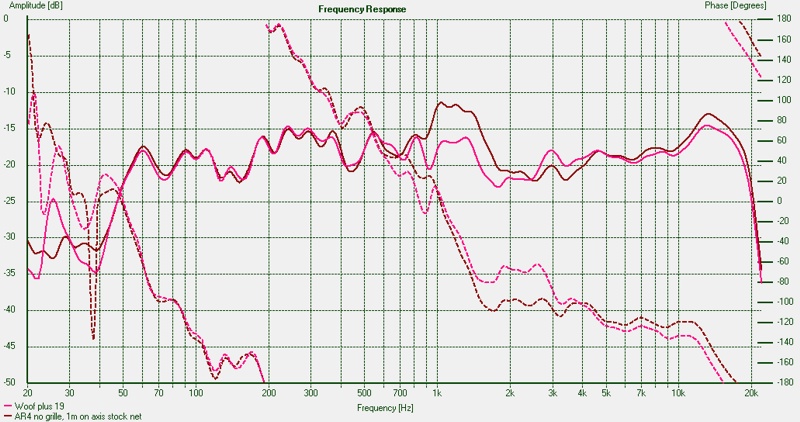
-
Crossover mods for the AR4x
speaker dave replied to speaker dave's topic in Mods, Tweaks, and Upgrades to the Classics
Here was about the best I could get with a 2nd order tweeter network. It used a 22uF input capacitor with a .274mH inductor to ground and finally a 4 ohm resistor to pull down the top end. The exactness of those values isn't important. It's just what I had on hand. So that is the hot tip if you want to try a simple improvement to your AR4x: add an inductor from between the 20 uF capacitor and the level pot, to ground. Use any inductor between .25 and .3mH and you should get reasonably close to the curve shown. Note that the bump at the top of the woofer range is gone and the 2k hole is a little better, but by no means dead flat. I'm really starting to think that a third order network is what is called for. David
-
Crossover mods for the AR4x
speaker dave replied to speaker dave's topic in Mods, Tweaks, and Upgrades to the Classics
Here are the same two tweeter curves compared to the woofer. The orange phase curve for the woofer is below the green phase curve of the first order tweeter network. What we would really like to see is the phase curves being close over the range where both units (woofer and tweeter) have significant output. Say 700 to 3000Hz. Beyond that one unit or the other has rolled off to the point where its phase doesn't matter. Orange and green curves are about 30 degrees apart so those sections would add fairly well in phase. Changing to the second order network pushes the phases apart to the point where they average about 90 degrees. Thats about the worst case possible. Flipping the phase of the tweeter won't help, due to the 180 phase reversal it would just become 90 degrees apart in the other direction. Note that these phase curves only apply for the exact microphone position they were measured at, in this case half way between the woofer and tweeter and about 1 meter out. If you move the microphone up from that position then the woofer phase will bend down and the tweeter phase up. Move the mic down and vice versa. The 90 degree phase discrepency would therefore cause unsymetrical lobing. The solution? Maybe a third order network would get the units near 180 degrees apart and then a polarity flip would get them quite close (tune in to part 3).
-
Crossover mods for the AR4x
speaker dave replied to speaker dave's topic in Mods, Tweaks, and Upgrades to the Classics
Here are some looks at a second order (12dB/octave) network for the tweeter section. Remember that the tweeter response is presenting some problems. It is a little underdamped giving a significant bump at 1200 Hz. A little higher at 2kHz there is a significant hole. With a simple network you have to find some type of compromise between too much 1200Hz energy, leading to a "midrange snarl" type of balance, or a hole at 2k. A higher order network will allow a squarer electrical corner that might give a better combined shape. Below is a comparison between a first order and second order network. The green curve is a 14uf (1st order) network similar to the aged cap in my system. The red curve is a second order network of about the right values to match the woofer. Note that I was able to bend the 1200Hz response down considerably while actually gaining a little at 2500. Not enough to fill in the 2k hole but at least moving in the right direction. The dashed curves show the effect of a higher order network on phase. Phase at the bottom corner of the tweeter bends upwards with the higher order network. Generally you should get 90 degrees more ultimate phase shift below the corner and about 45 at the corner for every order you add (1st to 2nd, 2nd to third, etc.). Because the rolloff corner is shifting upwards as well, we have about 60 degrees shift relative to the capacitor only network. Whats the right phase curve? Depends on what the woofer is doing.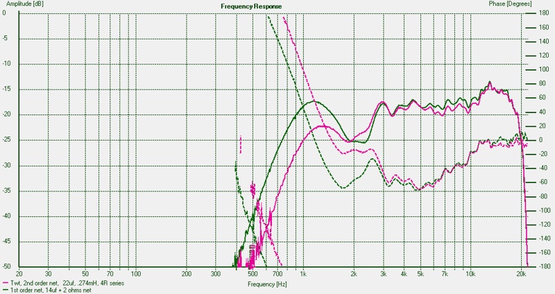
-
Crossover mods for the AR4x
speaker dave replied to speaker dave's topic in Mods, Tweaks, and Upgrades to the Classics
Hi Carl, I'll add a nearfield curve. The first box seems to leak considerably and I'll have to track that down. Unless that's just the way it is with an open dustcap? Regards, David -
Crossover mods for the AR4x
speaker dave replied to speaker dave's topic in Mods, Tweaks, and Upgrades to the Classics
They are full bandwidth unspliced. Holm seems to give you either the choice of time windowing or frequency smoothing, not both. I would think that time windowing with a little smoothing would be useful but it isn't an option. At 1 meter away, a 6th octave full range curve looked pretty reasonable. I also use the highpass function liberally to clean up hash in the tweeter curves. I think you've been working with this longer. Is there a way to splice with Holm? David -
Crossover mods for the AR4x
speaker dave replied to speaker dave's topic in Mods, Tweaks, and Upgrades to the Classics
If you wanted to stick with a first order network, this was a little better than stock. It is 10uF and reversed phase (reversed from as sold, but actually in-phase with the woofer). The overlap between drivers was less and and the 1200 Hz bump is gone but there is still a broad depression above. We can do better. Next time: a second order network. David
-
Crossover mods for the AR4x
speaker dave replied to speaker dave's topic in Mods, Tweaks, and Upgrades to the Classics
The stock network for an AR4x is 20uF on the tweeter, followed by the wirewound pots. The pot has the usual problems so I've bypassed it and plan to use fixed resistors for treble level. When I connected an external substitute for the internal network I noticed significant differences between the measured response of the internal 20uF and an external 20uF. Since the cap is 40 or so years old this isn't too surprising. Note that the capacitance seems to be down (loss at the low end of the tweeter) and there is loss up to 10k also. This would have to be due to higher ESR (effective series resistance). I'd note that many who restore these old speakers rush to replace all the caps. In this case a new cap will make a significant change but you have to wonder if it really is an improvement? If the pot is working you can have whatever treble level you like, but the replacement cap will raise the 1200 Hz bump, arguably not an improvement. (something to think about). Here I played with the external network values until I got a reasonable fit to the response of the internal part. 14uF and 2 ohms got the two curves to overlap so I have to assume that is the value, due to aging, of the AR unit. David

-
Crossover mods for the AR4x
speaker dave replied to speaker dave's topic in Mods, Tweaks, and Upgrades to the Classics
I thought I would try reversing the tweeter polarity to see what the sum is like. Note that the stock network has the tweeter out of phase with the woofer. Best phasing in a system depends on a lot of variables including woofer depth, crossover order, crossover frequency, etc. you can't generalize and generally must use the phasing that gives the best addition. As I mentioned it isn't good to achieve flat response via cancelation but it was worth a look. Here it might be worth listening to as it knocks about 7dB out of the peak and leaves a less offensinve trough around 2k. Here is a look at the effect of the grille. It is surprisingly minor with just a little bit of loss at 5k and 8k with the grille on. This indicates that the standard cloth is very transparent. Also that reflections off the side of the grille are minor. I suspect that the tweeter being fairly directional helps reduce the side reflections. David

-
Crossover mods for the AR4x
speaker dave replied to speaker dave's topic in Mods, Tweaks, and Upgrades to the Classics
I ran across this curve on the Stereophile website. It illustrates the problem of a first order network on the tweeter. While first order (a series capacitor) should give a 6dB per octave electrical rolloff, this only works well when the load is a resistor. When the load is a tweeter and its realworld impedance curve, then things won't be so tidy. At the tweeter's resonance its impedance will go quite high. This is a "light load" on the network and the voltage will rise also (in the graph the bump at 500Hz). At frequencies above that, the tweeter impedance will drop to near its DC resistance and voltage at the tweeter terminals will fall. Finally, at highest frequencies the inductance will bring the tweeter impedance up again and the voltage will rise again. One solution for this would be a Ferrofluid of the heavy damping type. It would drop the impedance rise at resonance (lower Qm) and give a more classic highpass. For these reasons text book crossovers are never very successful. A software based approach must always bring driver impedance into the calculations as the load on any proposed network. Anyhow, this shows the individual curves again plotted with the combined response of the whole system. The dark curve is the system response, the combination of the green and magenta woofer and tweeter. Again you can see that where the individual curves overlapped excessively the summed response shows the midrange peak. David

-
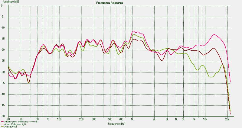
My local vintage audio dealer had a nice pair of AR4x's a few months back. Grilles and cabinets were in great shape and the drivers looked unmolested, but the tweeters were dead. Thanks to JKent and Zilch I now have new tweeters (from opposite coasts) and rather than put the system back together stock I want to see what I can do to improve the crossover network. Before all that lets take a look at the stock system to see what our $58 bought us in the late 60s. This is my first run with the Holm measuring system mentioned in the kitchen. So far it is a very handy FFT (with MLS) measuring system. Better than the PC RTA system I've been using, it gives true phase and lets you time window in a number of ways. Very cool. The first curve is the system at 3 angles, 30 degrees left, 0 degrees and 30 degrees right. This is from about 1 meter away with the grille off (grille on was surprisingly similar). I've seen other curves on the web and they are similar. Response is level from 50 Hz or so up to a "significant" bump at 1000 to 1500, followed by a 2kHz dip and finally a significant bump above 10k. I was hoping that the 2k hole was cabinet edge related because then some discrete damping under the grille could improve it. The fact that it doesn't change with lateral shift suggests it is inherent in the tweeter. This curve shows the individual parts, the woofer and tweeter. The woofer curve (orange) looks great and has a clean rolloff even with a simple network of inductor only. AR obviously worked hard to get a woofer with a smooth roll-off rather than the typical peak. For the tweeter the 2k dip is much more obvious here in the individual sections curve. It's easy to see where the 1200Hz peak comes from. For 2/3 of an octave the woofer and tweeter both have full strength. Overlap between units is not a good thing. The dashed curves are the phase curves for the two units (orange dashed = woofer, green dashed = tweeter). The actual phase curve of the units doesn't matter but the realative phase between the units is very important, especially in the crossover range where they both have about the same energy. The system response is the vector sum of the two sections so if there phase curves are close, their outputs add fully. If there phase curves approach 180 degrees apart then they will cancel rather than add. In our case the curves are within 30 degrees of each other in the 1 to 2k region so we will get full addition, i.e. a bump. If we could somehow spread the phases we might getl less bump but that isn't a good solution because at other vertical listening angles they would come back into phase. I'm guessing the original designers struggled with a compromise between the bump at 1200 and the dip at 2k. Pulling down 1200Hz would make the range above sag lower. This is compounded with a first order network (series cap) where the unit may roll off as intended, but at resonance where the driver impedance bumps up, the voltage after the cap bumps up as well. A higher order network would give more degrees of freedom hence better control of shape. David